Ring Counter PCB
Overview
A simple ring counter design that I made using a 4-bit counter (SN74LS161A) and a demux (SN74LS138) to output one of eight possible outputs. I will later use it with a shift register to create a 8x8 LED matrix driver
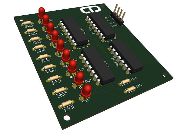
The project emerged from my frustration with my old 8x8 LED matrix driver that I made using 2 shift regisers (SN74HC595), which worked. But I hated the fact that I shifting in a single bit into one of the regisers to control the columns which felt like a waste.
Key Features
- Tri-State buffer to control the different clock signals.
- The LEDs use a common power so not gates are not needed.
Challenges & Solutions
Challenge: Only wanting to use 2 data pins max, as my other 8x8 matrix driver use 3 data pins.
Solution: Use a tri-state buffer to disconnect the clock pin from the counter IC and allow the clock pin to drive the clock LED.
Challenge: Getting it to work.
Solution: As this was my first PCB I didn't really know what I was doing, so I did forget 2 traces. But after soldering two wires on the back it works great.